Over-extrusion
PIDs autotune
Temperature settings
Stringing
Belt tension
BED PID – IMPORTANT!!!
Hello and welcome to troubleshooting guide for famous model All In One 3D printer test! This guide should help you to tune your 3D printer as much as is it possible, so let’s dive right into it!
-
-
Over-extrusion
-
- Over-extrusion
The most common issue I see on my model in „made“ section is over-extrusion caused by non-calibrated extruder…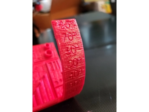
Upload by Nitro66215 Here you can see classic example of over-extrusion, printer spits out too much of a plastic resulting in visible horizontal lines and overall bad quality.
But how can I calibrate my extruder?
It’s not that hard. First of all, you need to connect your printer to some interface with terminal. It’s best idea to use so called „Octoprint“, but not everyone has access to Raspberry Pi / Zero. You can use software like „pronterface“, but everything with terminal will work. After you connect your printer to PC / Mac via USB cable, run command „M503“ which will show you your current EEPROM values. In M92 section you can see values which declares steps per mm, these are really important, especially „E“ one. Next step depends on your extruder…… if you have direct … you simply heat up your nozzle to 190C (PLA) or 240C (ABS) and measure 120mm from point where extruder „eats“ filament. Be sure to mark this part with marker or tape, you’ll need this point as reference. Then send G1 E100 F100 command into your printer via terminal and wait, until your extruder stops extruding. After this, measure distance between point where extruder „eats“ filament and marked point, your result should be something close to 20mm. If it’s more or less, your extruder isn’t calibrated properly and you have to calculate deviation. First simply subtract measured distance from 120mm, if you measured something like 15mm you will get 105mm as a result. Then proceed to next step.
… if you have bowden … you simply heat up your nozzle to 190C (PLA) or 240C (ABS) and unload your filament. Next unplug your PTFE tube from your extruder and push filament thru „naked“ extruder, so It leaks out from fitting coupler. Then cut the filament with sharp blade parallel to the fitting and run G1 E100 F100 command. After your extruder stops extruding, cut filament parallel way to the fitting nut again. Now measure the distance of your cut piece of filament, it should be close to 100mm long, if it isn’t, your extruder isn’t calibrated properly and you should continue to next step.
If you’ve got to this point, you have to calibrate deviation, because your extruded piece wasn’t exactly 100mm. Deviation is calculated by simple formula – deserved length / observed length * E steps per mm. I can show you this on our 105mm example: 100mm / 105mm * E200.00 = E190,47 where result is new number of steps per mm.
Now, when you’ve calculated correct value for your extruder, it’s time to write it into EEPROM. Simply send command M92 Ex.xx (where Ex.xx is your new value, in my case E190,47), then send M500 command. In the end you should see new value in M92 section when you send M503 to load your EEPROM again. You may want to repeat this process few times to achieve best results!
- Over-extrusion
PIDs autotune
-
- PIDs – temperature stability
Second really common issue I can see on most of uploads is bad temperature stability cause by both non-calibrated or disabled PIDs.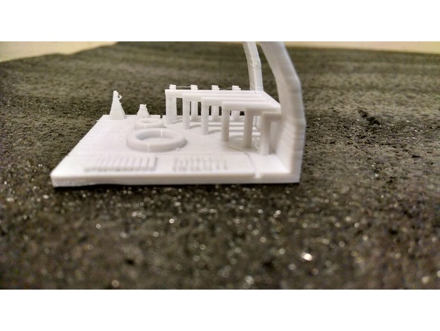
Upload by Lumley Here you can see typical example of bad temperature stability and possibly non-calibrated extruder.
But how do I tune my PIDs?
Luckily, it’s quite easy! First you have connect to your printer via terminal, you can use Octoprint, Pronterface or other softwares to do so..! After your printer is connected to your PC / Mac, you can start tuning your PIDs.First home your printer on all axes (X, Y, Z) and then move your Z axis 10mm up and X and Y to mid of your print bed. After this turn on your blower fan by sending M106 (M106 S255) command to your 3D printer via terminal and proceed to next step.
Now it’s turn to run PID autotune. First, be sure that your blower fan is running on max speed! Next, send M303 E0 C8 S210 command to your printer, M303 declares PID autotune command, E0 is number of extruder (E-1 is bed, E1 is second extruder), C8 is number of PID calibration cycles and S is desired temperature. If print ABS or PETG most of the time, you can use S240 (or different value).
Now wait few minutes until you see „PID autotune done“ in terminal. Below you’ll see new Kp, Ki and Kd values. For example: Kp 21.00, Ki 1.25, Kd 86.00. You have to write these values to EEPROM now. You can do this by downloading „Marlin EEPROM editor plugin for Octoprint“, or use M301 command. In my case I’ll use it like this: M301 P21.00 I1.25 D86.00 (Kp = P, Ki = I, Kd = D) and then save EEPROM by M500 command. You can check, that you’ve done everything right by reading EEPROM values with M503 command. If you see your PID values there under M301 section, everything should be correct!
- PIDs – temperature stability
Temperature settings
-
- Best temperature settings
It’s quite important to find best temperature settings for your filament, in this article I’ll explain you best way to so! This can affect loads of things including overhangs and bridging!First of all, you have to download / create some model of so called „temperature tower„. This is – well – tower, which changes temperature of your hotend every X mm’s. By this, you can save some time and see what temperature does perform
best.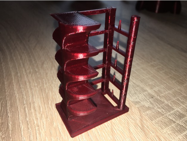
Temperature tower by 3dMakernoob. My most favorite model is temperature tower by 3DMN (3D Makernoob), you can find it on this link.
But how do I setup my slicer to change temperature every X layers?
Well, this clearly depends on your slicer. If you have Simplify3D for example, you can simply set different temperatures every X layer in „temperature“ tab.I personaly use Cura, so I’ll try to give you an idea how to setup Cura for temperature tower, but I guess that it’ll be similar in other slicers as well.
First of all import your .stl model to Cura, then set your temperature, layer height, initial layer height, infill,… and slice your model. Then set your view mode to „layer view“ and adjust slider to find first place, where temperature should change for the first time. Write down number of this layer and continue this way all the way up to the end.
When you have written down all numbers of layers, where temperature should change, go to Extensions -> Post processing -> Modify G-Code, then click „Add a script“ and click „ChangeAtZ“. Type here number of first layer, where temperature should change, then check „Change extruder 1 temp“ and set your first temperature here. Continue so with the rest.
In the end, slice your model again and export G-Code and give it shot on your 3D printer! If you’ve done everything correctly, you should see how temperature chages on display during print. As a result you’ll get tower with multiple bridges, overhangs and other features where you should be able to see difference every temperature change. Stick to the temperature value you consider as the best one.
- Best temperature settings
Stringing
-
- Stringing
Stringing is one of the annoying common issues I see a lot, luckily it’s really easy to fix!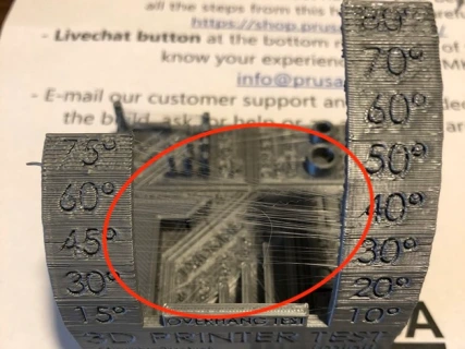
Upload by ReturnZero This is – I’d say – quite a good example of stringing. Stringing happens when there is too much pressure in extruder and melted plastic leaks out during movement in free space. There are 3 majors values, which you are going to adjust to remove stringing : retraction, temperature and travel speed.
First of all, you wan’t to be sure that you have retractions turned on in your slicer software. You want to start with some lower values like 2mm retraction and 30mm/s retraction speed. Then you should print some retraction tests like this one:
https://www.thingiverse.com/thing:2563909
to see if you need more retractions. If you see only small blobs on these two columns, lower your temperature bit and increase travel speed up to 150mm/s.If you still see some strings, increase retraction distance in speed, this is must especially with bowden extruder.
NOTE: Some fillaments may need higher retraction settings, PET-G is known for stringing and strings of some PET-G’s can’t be removed at all.
And that’s it! Say goodbye to strings!
- Stringing
Belt tension
-
- Belt tension
Belt tension of printer can be quite a problem when you don’t know how to tense your belts correctly. You can run into some layer-shifting and ringing issues. It may seem obvious that belt should be tense as much as it is possible, but – well – things aren’t that easy actually.First of all, be sure that your idler on motor shaft is aligned in axis with belt holder on carriage and idler on second side. Small tip – you can use either toothed or non-toothed idler on tensioner side, it makes no difference. If motor idler isn’t aligned, just loose small black screws on idler and move it to proper position.When everything is okay, loop your belt between motor idler and tensioner idler. From my testing, belt-type doesn’t affect print quality, but high-quality rubber belts with stainless steel can definitely last longer.Now to the tensioning. Lot of people think, that more belt tension = better quality. That isn’t truth at all. The perfect belt tension is, when the belt isn’t really tight but teeth on won’t slip at all. Be sure, that you can normally push the belts together with your fingers, but when you move the carriage by a hand, everything should be smooth, no bumps, no weird sounds. To find this perfect spot I’d suggest you to search on Thingiverse for belt tensioners that will fit your 3D printer!
BED PIDs = Z lines?!
- Bed PID? Important!!!
Have you ever met artifact visible in terms of Z lines, layer inconsistency, bad tolerances or poor top layer looking like plastic was melted under low or high temperature?I know it sounds bit „weird“, but this can be due to the incorrect bed pid tuning or so stock bed temperature control. We’ll talk about this in a minute, now let’s see, how the issue looks like.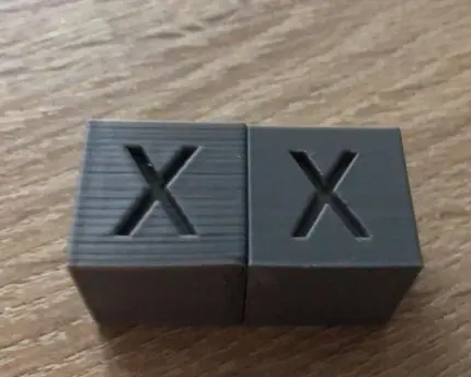
Perfect example of BED pid issue. On the image you can see bad BED PIDs on the left and correct ones on the right. One small difference in the settings, almost unbelievable difference in output quality. But why? And how?
To be honest, I don’t exactly understand why does this happen, some people are talking about induction on power bed cables, where flows kinda lot of current under 12/24V, but most of people say that this is due to the current „backslash“ when PIDs aren’t dialed in, this backslash then goes back to the PSU and directly to the motherboard, where it affects drivers and logical convertors. Not sure which version is correct (if some of them even is correct), but less talking, now to the easy fix.
There are two, basically three ways to fix it. First one is obvious – turn off the bed (just for testing purposes while printing small PLA / PETG objects). I personally recommend to unplug one of the wires in bed circuit completely, just to be sure. If result of all this is noticeably better quality, congrats, you found the issue you were searching for. If not, read through some other posts on this guide, you may find fix there. Now to the better fix – PID tuning.
First of all you should enable bed PID in your 3D printer (marlin) firmware if you haven’t done so. You’ll find this in „configuration.h“ file. Next you should open „configuration_adv.h“ file and decrease WATCH_BED_TEMP_PERIOD to 120 or below. If you don’t change this value, you’ll meet common bug in a minute.
Now connect to your printer with some software which supports terminal connection, move your print head to mid of the bed and like 20mm/s above bed, then turn on fans. Next send M303 E-1 S60 C6 command to your printer. Your bed should now heat up and cool down 6 times (C parameter). After this all you should receive three values, Kp, Ki and Kd. Write this values with M301 command (syntax: M301 P10 I2 D5) and you are done! Now print your test cube / any other model again, you should see improvement right a way!
Now to the third, cleanest, but most expensive fix. It’s simple. Get second PSU and external Mosfet. Nothing more to say, this method should, I say should, I am not even sure if this works, best of all three.
I hope that this helped you to fix your issue!
- Belt tension
-
-
